Back to
Contents Page
Dell Inspiron 4000
 |
NOTICE: Only a
certified service technician should perform repairs on your computer.
Damage or inoperability due to servicing not authorized by Dell is not
covered by your warranty. |
|
NOTICE: Unless
otherwise noted, each procedure in this manual assumes that a part can be
replaced by performing the removal procedure in reverse order.
|
|
NOTICE: To avoid
damaging the computer, perform the following steps before you begin
working inside the computer. |
- Make sure that the work surface is clean to
prevent scratching the computer cover.
- Save and close any open files, and exit any
open programs.
 |
HINT: Make sure the
computer is turned off and not in standby or hibernate mode. If you cannot
shut down the computer using the computer's operating system, press and
hold the power button for 4 seconds. |
- Turn off the computer and all attached
devices.
- Make sure the computer is undocked.
- Disconnect the computer from the electrical
outlet.
- To avoid possible damage to the system board,
wait 10 to 20 seconds and then disconnect any attached devices.
- Disconnect all other external cables from the
computer.
- Remove any installed PC Cards or plastic
blanks from the PC Card slot.
- Close the display and turn the computer upside
down on a flat work surface.
- Remove the primary battery from the battery
bay and the secondary battery from the modular bay, if a secondary battery is
in use.
|
NOTICE: To avoid
damaging the system board, you must remove the main battery and secondary
battery (if present) before you service the computer. |
- Remove any installed device in the modular
bay.
- To dissipate any static electricity while you
work, periodically touch an unpainted metal surface on the computer, such as
the I/O panel on the back of the computer chassis.
- Handle components and cards with care. Do not
touch the components or contacts on a card. Hold a card by it edges or by its
metal mounting bracket. Hold a component such as a microprocessor by its
edges, not by its pins.
The procedures in this manual require the following tools:
- #1 magnetized Phillips screwdriver
- Small flat-blade screwdriver
- Small plastic scribe
- Microprocessor extractor
- Flash BIOS update program floppy disk or CD (required only when upgrading
the microprocessor, replacing the reserve battery, or replacing the system
board)
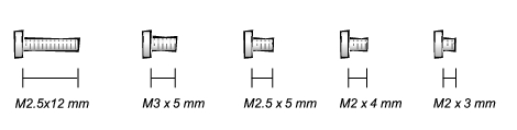
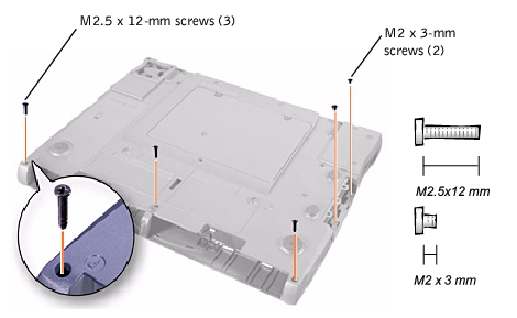
When you are removing and replacing components, photocopy the screw placemat
as a tool to lay out and keep track of the component screws. The placemat
provides the number of screws and the sizes.
|
NOTICE: When
reinstalling a screw, you must use a screw of the correct diameter and
length. Make sure that the screw is properly aligned with its
corresponding hole, and avoid over tightening. |
Screw Placement
|
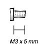
Hard Drive Door Security:
M3 x 5 (1 each)
|
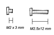
Keyboard to Bottom Case Assembly:
M2.5 x 12 (5 each)

|
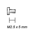
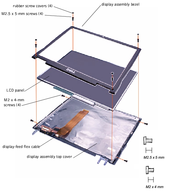
LCD Display Bezel:
M2.5 x 5 (4 each)
Rubber Screw
Covers (4 each)
|
|
LCD Hinge Bracket to Bottom Case Assembly:
M2.5 x 5 (5 each)
|
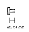
14.1-Inch LCD Display Assembly and Flex-Cable Retention Bracket to Top
Cover:
M2 x 4 (5 each)
|
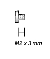
Display Assembly EMI Shield Bracket:
M2 x 3 (5 each)
|
|
Palm Rest to
Bottom Case Assembly:
M2 x 3 (5 each)
M2.5 x 12 (3 each)
|
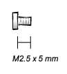
Hybrid Cooling Fan:
M2.5 x 5 (2 each)

|
System Board
to Bottom Case Assembly:
M2.5 x 5 (10 each)

|
- Save and close any open files, exit any open
programs, and shut down the computer.
- If the computer is connected (docked) to an
advanced port replicator (APR), undock it.
- Keep the display open and tilt the computer
back so that you can access the bottom of the computer.
- Slide and hold the latch release on the left
side, and remove any device installed in the modular bay.
- Slide and hold the latch release on the right
side, and remove any battery installed in the battery bay.
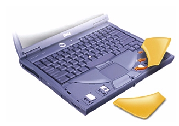
- Locate the orange palm rest removal buttons.
Firmly press the buttons with the eraser end of a pencil (or a dull utensil
smaller than your finger) to release the palm rests.
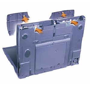
- Remove the palm rests.
- To replace the palm rests, insert the tabs on
the inside edge of the palm rest into the slots on the computer. Then press
along the outside edges of the palm rest until it snaps into place.
Repeat the process on each side.
- Slide your index fingers under the straight
edge of the display cover until the cover pops out.
- Slide the display cover towards the back of
the computer.
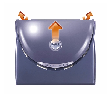
- User your fingers to release the cover
completely, and remove it.
- To replace the display cover, bend it slightly
to insert the four tabs on the rounded edge of the cover into the slots on the
top of the computer.
- Press the cover along the straight edge at the
back of the computer until it snaps into place.
- Firmly press the Dell logo until it snaps into
place. Press above both hinge covers to engage the final snaps.
|
NOTICE: The hard drive
is very sensitive to shock. Handle the assembly by its edges (do not
squeeze the top of the hard drive case), and avoid dropping it.
|
|
NOTICE: Disconnect the
computer and any attached devices from electrical outlets, and remove any
installed batteries. |
|
NOTICE: To avoid ESD,
ground yourself by using a wrist grounding strap or by touching an
unpainted metal surface on the computer. |
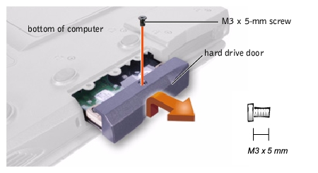
- Remove the screw from the hard drive door.
- Slide the drive door up until the drive
assembly tabs disengage from the door slots in the bottom case assembly.
- Pull the drive assembly straight out of the
bottom case assembly.
- Push the drive assembly into the hard drive
opening of the computer.
- Align the drive assembly tabs with the bottom
case assembly slots and push down until it clicks into place.
- Replace the screw in the drive door.
|
NOTICE: Disconnect the
computer and any attached devices from electrical outlets, and remove any
installed batteries. |
|
NOTICE: To avoid ESD,
ground yourself by using a wrist grounding strap or by touching an
unpainted metal surface on the computer. |
- Close the display, and turn the computer
upside down on a flat work surface.
- Slide the modular bay latch toward the right.
- Keep holding the latch open while you pull the
device out of the modular bay with the other hand.
|
NOTICE: The only time
you should ever access the inside of your computer is when you are
installing memory modules or a Mini PCI card. |
|
NOTICE: Disconnect the
computer and any attached devices from electrical outlets, and remove any
installed batteries. |
|
NOTICE: To avoid ESD,
ground yourself by using a wrist grounding strap or by touching an
unpainted metal surface on the computer. |
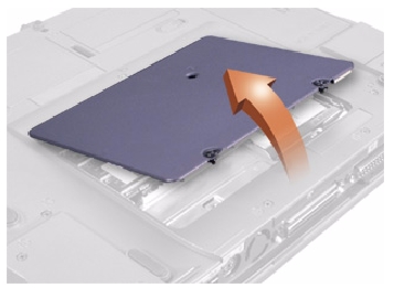
- Remove the memory module cover:
|
HINT: The screw labeled
with the "circle K" in the middle of the memory module cover secures the
keyboard assembly and does not secure the memory module cover.
|
- Use a coin or flat-blade screwdriver to
release the two captive screws that secure the memory module cover.
- Place your finger under the cover at the
indentation and lift and slide the cover open.
|
NOTICE: Disconnect the
computer and any attached devices from electrical outlets, and remove any
installed batteries. |
|
NOTICE: To avoid ESD,
ground yourself by using a wrist grounding strap or by touching an
unpainted metal surface on the computer. |
- Remove the memory
module cover.
|
NOTICE: Handle memory
modules with care. Do not touch the components on a module. Hold the
module by its edges. |
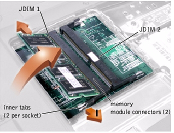
- To release a memory module from its connector,
spread apart the inner tabs of the memory module connector just far enough for
the memory module to disengage from the connector. The module should pop up
slightly.
- Lift the memory module out of its connector.
- If you only have one memory module, install it
in the connector labeled "JDIM1." If you have two memory modules, install the
second module in the connector labeled "JDIM2."
|
HINT: Memory modules
are keyed, or designed to fit into their connectors, in only one
direction. |
- Align the memory module's edge connector with
the slot in the center of the memory module connector. With the module at a
45-degree angle, press the memory module's edge connector firmly into the
memory module connector.
- Pivot the memory module down until it clicks
into place. If you do not hear a click, remove the memory module and reinstall
it.
- Insert the tabs on the memory module cover into
the bottom case assembly. Rotate the memory module cover down and tighten the
two captive screws.
|
NOTICE: The only time
you should ever access the inside of your computer is when you are
installing memory modules or a Mini PCI card. |
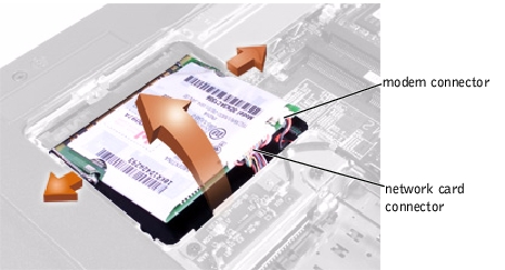
The optional Mini PCI card assembly may contain either a modem, network
adapter, or combination of both. You must remove the Mini PCI card subassembly
before the system board assembly can be removed. The Mini PCI card subassembly
must be connected to the internal antenna for proper operation.
|
NOTICE: Disconnect the
computer and any attached devices from electrical outlets, and remove any
installed batteries. |
|
NOTICE: To avoid ESD,
ground yourself by using a wrist grounding strap or by touching an
unpainted metal surface on the computer. |
- Remove the memory
module cover.
- To release a Mini PCI card subassembly from its
connector, spread apart the inner tabs of the connector just far enough for
the Mini PCI card assembly to disengage from the connector. The module should
pop up slightly from the interface connector.
- Lift the Mini PCI card subassembly out of its
connector and disconnect any attached cables.
- Align and press the Mini PCI card subassembly
into the system board interface connector.
|
HINT: A modem-only Mini
PCI card has only one cable and connector. |
- Connect the interface cables.
- Replace the memory module cover.
|
NOTICE: Disconnect the
computer and any attached devices from electrical outlets, and remove any
installed batteries. |
|
NOTICE: To avoid ESD,
ground yourself by using a wrist grounding strap or by touching an
unpainted metal surface on the computer. |
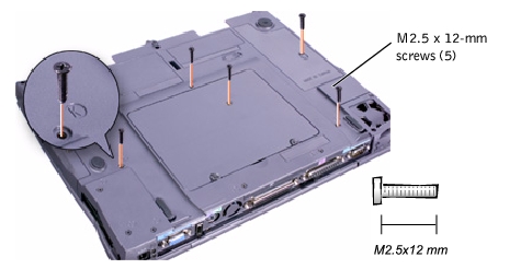
- Remove the hard
drive assembly.
- Turn the computer bottom-side up, and remove
the five screws labeled with a "circle K."
- Turn the computer right-side up and open the
display.
|
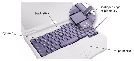
NOTICE: The key caps on
the keyboard are fragile, easily dislodged, and time-consuming to replace.
Be careful when removing and handling the keyboard. |
- Insert a small, flat-blade screwdriver or
plastic scribe into the scalloped edge next to the right <Shift> key,
and release the keyboard from the palm rest assembly.
- Lift the keyboard straight up until it clears
the keyboard boss support in the bottom case assembly.
- Rotate the keyboard forward toward the front of
the computer.
- Rest the key face of the keyboard on the palm
rest.
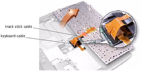
- Disconnect the keyboard flex cable from the
interface connector on the system board assembly by pulling up on the
connector.
- Remove the keyboard assembly from the bottom
case assembly.
- Place the keyboard on the palm rest at the
front of the computer with the keys facing down and the connector toward the
back of the computer.
- Connect the keyboard flex cable to the
interface connector on the system board assembly.
|
NOTICE: Position the
keyboard cable so that it does not pinch when you replace the keyboard in
the bottom case assembly. |
- Carefully turn the keyboard over and fit the
keyboard into place.
- Check that the keyboard is correctly
installed. The keys should be flush with the left and right surfaces of the
palm rest.
|
NOTICE: Make sure that
the keyboard is aligned correctly to avoid stripping the screws the next
time they are removed. |
- Reinstall the five M2.5 x 12-mm screws in the
holes labeled "circle K."
|
NOTICE: You must remove
the display assembly before you remove the palm rest assembly; the display
assembly hinges pass through the back of the palm rest assembly.
|
|
HINT: Always remove and
replace the LCD panel as a complete assembly. |
|
NOTICE: Disconnect the
computer and any attached devices from electrical outlets, and remove any
installed batteries. |
|
NOTICE: To avoid ESD,
ground yourself by using a wrist grounding strap or by touching an
unpainted metal surface on the computer. |
- Remove the hard
drive assembly.
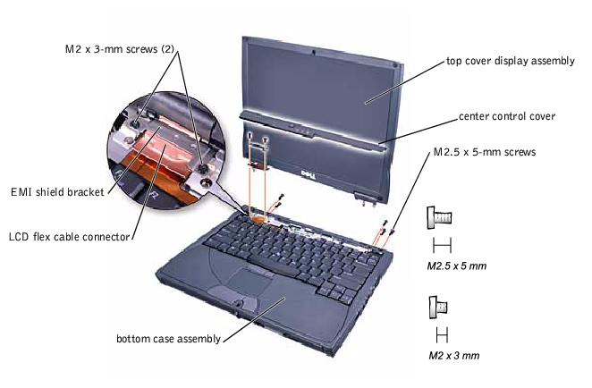
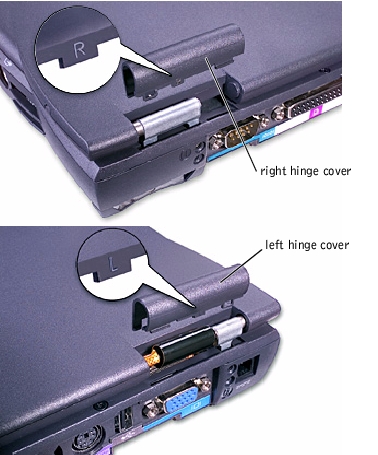
- Remove the center control cover:
- Use a scribe to lift the right edge of the
center control cover and pry it loose from the bottom case assembly.
- Lift the center control cover up and away
from the bottom case assembly.
- Close the display. From the back of the
computer, remove the five screws labeled with the "circle D." There are two
screws on the right hinge and three screws on the left hinge.
- Open the display assembly approximately 90
degrees, and support the display assembly so that it does not open past this
position.
- Remove the two M2 x 3-mm screws that secure
the EMI shield bracket (metal) to the system board assembly.
- Remove the flex cable EMI shield retention
bracket that covers the display flex cable connector on the system board.
- Pull straight up on the loop attached to the
interface cable connector to disconnect the display flex cable from the system
board.
- Lift the display assembly from the bottom case
assembly.
|
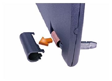
HINT: The right plastic
hinge cover is labeled "R" and the left plastic hinge cover is labeled
"L." |
- Remove the right and left plastic hinge covers
from the hinges.
|
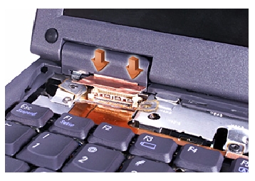
NOTICE: When
reconnecting the display-feed cable connector to the system board, push
down on the top left and right ends of the connector. Pressing on the
center of the connector might damage resistors and compromise EMI
protection in the computer. |
|
NOTICE: Disconnect the
computer and any attached devices from electrical outlets, and remove any
installed batteries. |
|
NOTICE: To avoid ESD,
ground yourself by using a wrist grounding strap or by touching an
unpainted metal surface on the computer. |
- Remove the hard
drive assembly.
- Remove the display
assembly.
- Use the scribe to pry the four rubber screw
covers out of the screw holes located at the four corners of the bezel on the
front of the display assembly.
- Remove the four M2.5 x 5-mm screws located at
the corners of the bezel on the front of the display assembly.
|
NOTICE: Some of the
bezel snaps may be difficult to remove, so be careful when separating the
bezel from the display assembly. |
- Use a plastic scribe and separate the bezel
from the display-assembly top cover.
- Be careful not to lose the display magnet on
the right side of the back cover. The polarity of the magnet is marked with a
minus "" sign and oriented toward the bottom of the display. Make sure to
replace the magnet in the same orientation when you reassemble the display.
|
NOTICE: Disconnect the
computer and any attached devices from electrical outlets, and remove any
installed batteries. |
|
NOTICE: To avoid ESD,
ground yourself by using a wrist grounding strap or by touching an
unpainted metal surface on the computer. |
- Remove the hard
drive assembly.
- Remove the display
assembly.
- Remove the display
assembly bezel.
- Remove the two M2 x 4-mm screws on the left
side of the LCD panel and the two M2 x 4-mm screws on the right side of the
LCD panel.
- Remove the M2 x 4-mm screw that secures the
display flex cable to the display assembly through the flex-cable retention
bracket (black plastic).
- Lift and rotate the top of the LCD panel out
of the top cover.
|
HINT: Use a magnetic
screwdriver to reassemble the LCD panel in the display, and secure the
right side first. Make sure to replace the magnet with the minus sign
toward the bottom of the display. |
- Place the bottom edge of the LCD panel in the
bottom of the top cover, and elevate the top of the panel with your hand.
- Lay the LCD panel in the top cover.
- Reinstall the five M2 x 4-mm screws securing
the LCD panel to the top cover.
|
NOTICE: Disconnect the
computer and any attached devices from electrical outlets, and remove any
installed batteries. |
|
NOTICE: To avoid ESD,
ground yourself by using a wrist grounding strap or by touching an
unpainted metal surface on the computer. |
- Remove the hard
drive assembly.
- Remove the display
assembly.
- Remove the display
assembly bezel.
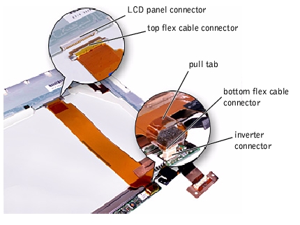
- Remove the tape that covers the connector to
the LCD panel located at the top of the display-feed flex cable.
- Hold the connector at the top of the
display-feed flex cable, and pull down and away to remove it from the LCD
panel.
|
NOTICE: Disconnect the
computer and any attached devices from electrical outlets, and remove any
installed batteries. |
|
NOTICE: To avoid ESD,
ground yourself by using a wrist grounding strap or by touching an
unpainted metal surface on the computer. |
- Remove the hard
drive assembly.
- Remove the display
assembly.
- Remove the display
assembly bezel.
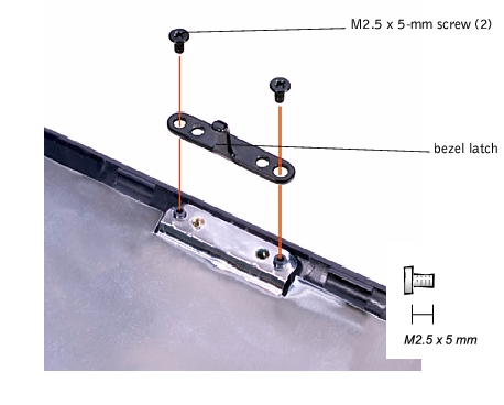
- Remove the display assembly bezel latch by
removing the two M2.5 x 5-mm screws that secure it to the display assembly top
cover.
- Remove the display
assembly.
- Remove the plastic hinge covers from the
hinges.
- Attach the display assembly to the bottom case
assembly.
|
HINT: The right hinge
cover is labeled "R," and the left hinge cover is labeled "L." The labels
face the back of the computer. |
- Close the display assembly and snap the hinge
covers in place over the hinges.
|
NOTICE: Disconnect the
computer and any attached devices from electrical outlets, and remove any
installed batteries. |
|
NOTICE: To avoid ESD,
ground yourself by using a wrist grounding strap or by touching an
unpainted metal surface on the computer. |
- Remove the hard
drive assembly.
- Remove the keyboard.
|
NOTICE: You must remove
the display assembly before you remove the palm rest assembly; the display
assembly hinges pass through the back of the palm rest assembly.
|
- Turn the computer right-side up on the work
surface, and remove the display hinge
cover and display
assembly.
- Turn the computer over and remove the three
M2.5 x 12-mm screws labeled with a "circle P."
- Remove the five M2 x 3-mm screws that secure
the palm rest to the bottom case assembly:
- Remove the two M2 x 3-mm screws located in
the hard drive bay door and labeled with a "circle P."
- Remove the remaining two M2 x 3-mm screws
located on the back edge of the bottom case assembly, underneath the display
assembly.
- Turn the bottom case assembly over. Remove
the M2 x 3-mm screw located underneath the keyboard, on the right side of
the bottom case assembly, next to the microprocessor thermal cooling
assembly.
- Pull up on the loop attached to the palm rest
flex cable connector to remove it from the interface connector on the system
board assembly.
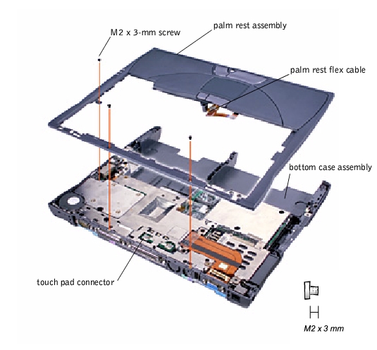
- Using the plastic scribe along the edge of the
plastic, remove the palm rest assembly from the bottom case assembly.
|
NOTICE: Disconnect the
computer and any attached devices from electrical outlets, and remove any
installed batteries. |
|
NOTICE: To avoid ESD,
ground yourself by using a wrist grounding strap or by touching an
unpainted metal surface on the computer. |
- Remove the hard
drive assembly.
- Turn the computer over and remove the keyboard
assembly.
- Remove the display
assembly.
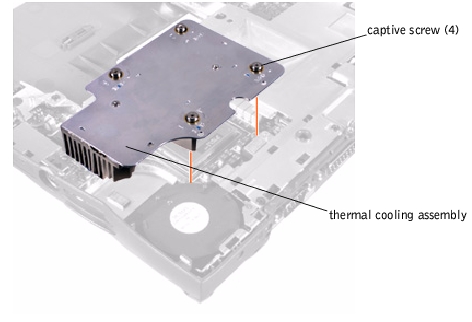
- Loosen the four captive screws securing the
microprocessor thermal cooling assembly.
- Remove the microprocessor thermal cooling
assembly from the system board assembly.
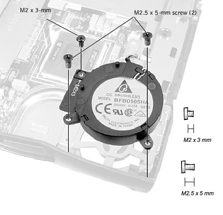
- Remove the two M2.5 x 5-mm screws and the one
M2 x 3-mm screw that secure the hybrid cooling fan to the system board.
|
HINT: The fan power
cable is long and can be pulled out from under the EMI shield to provide
access to the connector. |
- Disconnect the fan power cable from the system
board interface connector and remove the hybrid cooling fan.
 |
CAUTION: Do not
block the keyboard screw hole when reinserting the fan cable.
|
|
NOTICE: Hold the
microprocessor down while turning the cam screw to prevent intermittent
contact between the cam screw and the microprocessor.
|
|
NOTICE: Disconnect the
computer and any attached devices from electrical outlets, and remove any
installed batteries. |
|
NOTICE: To avoid ESD,
ground yourself by using a wrist grounding strap or by touching an
unpainted metal surface on the computer. |
- Remove the hard
drive assembly.
- Turn the computer over and remove the keyboard.
|
NOTICE: To ensure
maximum cooling for the microprocessor, do not touch the heat transfer
areas on the thermal cooling assembly. The oils in your skin reduce the
heat transfer capability of the thermal pads. |
- Remove the thermal
cooling assembly.
|
NOTICE: When removing
the microprocessor module, pull the module straight up. Be careful not to
bend the pins on the microprocessor module. |
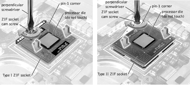
- Remove the microprocessor module:
|
NOTICE: To avoid
damaging the microprocessor while removing the cam screw, hold the
screwdriver so that it is perpendicular to the microprocessor.
|
- Use a small flat-head screwdriver and rotate
the ZIF socket cam screw 180 degrees to loosen the ZIF socket.
The ZIF socket cam screw secures the microprocessor assembly
to the system board assembly. Take note of the arrow on the ZIF socket cam screw
points to the front of the computer when engaged.
- Use a microprocessor extraction tool to
remove the microprocessor module.
|
HINT: To update or
reflash the BIOS, see the Dell Portable Computer BIOS Update Guide
for instructions. |
|
NOTICE: After replacing
the microprocessor module, update the BIOS using a flash BIOS update
program floppy disk or CD. |
|
NOTICE: Seating the
microprocessor module properly in the ZIF socket does not require force.
|
|
NOTICE: A
microprocessor module that is not properly seated can result in an
intermittent connection or permanent damage to the microprocessor and ZIF
socket. |
- Align the pin-1 corner of the microprocessor
module with the pin-1 corner of the microprocessor socket on the system board
and insert the microprocessor module.
|
NOTICE: You must
position the microprocessor module correctly in the ZIF socket to avoid
permanent damage to the module and the socket. |
When the microprocessor module is correctly seated, all four
corners are aligned to the same height. If one or more corners of the module are
higher than the others, the module is not seated correctly.
|
NOTICE: Hold the
microprocessor down while turning the cam screw to prevent intermittent
contact between the cam screw and microprocessor. |
- Tighten the ZIF socket cam screw to secure the
microprocessor module to the system board assembly.
|
NOTICE: The reserve
battery provides power to the computer's RTC and NVRAM when the computer
is turned off. Removing the battery causes the computer to lose the date
and time information as well as all user-specified parameters in the BIOS.
If possible, make a copy of this information before you remove the reserve
battery. |
|
HINT: To update or
reflash the BIOS, see the Dell Portable Computer BIOS Update Guide
for instructions. |
|
NOTICE: Disconnect the
computer and any attached devices from electrical outlets, and remove any
installed batteries. |
|
NOTICE: To avoid ESD,
ground yourself by using a wrist grounding strap or by touching an
unpainted metal surface on the computer. |
- Remove the hard
drive assembly.
- Remove the memory
module cover.
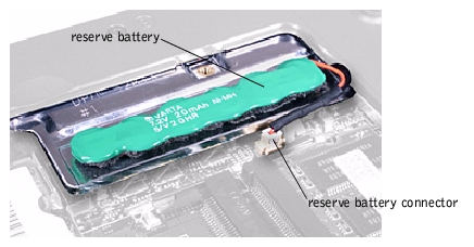
- Disconnect the reserve battery cable from the
connector on the system board assembly located next to the reserve battery.
- Remove the reserve battery from the EMI shield:
- Pry the reserve battery free from the foam
pad.
- Remove the remnants of the foam pad from the
EMI shield.
- Connect the reserve battery cable to the
connector on the system board.
- Position the reserve battery on the EMI shield
next to the connector to minimize slack in the cable.
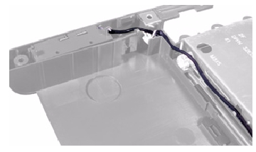
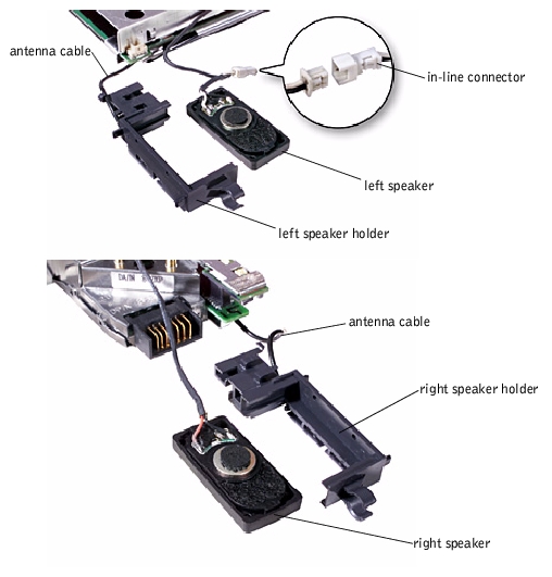
The system speakers are located on the front left and right sides of the
bottom case assembly. Each speaker assembly is marked with a right and left
label. Take note of the speaker cable routing in the bottom case assembly so
that you can replace it correctly.
|
NOTICE: Disconnect the
computer and any attached devices from electrical outlets, and remove any
installed batteries. |
|
NOTICE: To avoid ESD,
ground yourself by touching an unpainted metal surface or by using a wrist
grounding strap. |
- Remove the hard
drive assembly.
- Remove the keyboard
assembly.
- Turn the computer over and remove the display
assembly.
- Remove the palm
rest assembly.
- Remove the thermal
cooling assembly.
- Disconnect the speaker interface cable
connectors.
|
HINT: The left speaker
has an in-line connector, and its cable is shorter than the right speaker.
|
|
HINT: Speakers face out
in the bottom case assembly holders. |
- Remove the speaker assemblies by pulling them
straight up and out of the bottom case assembly.
- To replace the speaker assembly, place the
mounting ring over the front palm rest screw post.
- Slide the speaker assembly down into the
bottom case assembly.
The system board's BIOS chip contains the system service tag number, which is
also visible on a bar-code label on the bottom of the computer. The replacement
kit for the system board assembly includes a floppy disk that provides a utility
for transferring the service tag number to the replacement system board
assembly.
|
NOTICE: Disconnect the
computer and any attached devices from electrical outlets, and remove any
installed batteries. |
|
NOTICE: To avoid ESD,
ground yourself by using a wrist grounding strap or by periodically
touching an unpainted metal surface on the computer. |
- Remove the hard
drive assembly.
- Turn the computer over and remove the keyboard
assembly.
- Remove the display
assembly.
- Remove the palm
rest assembly.
- Verify that all PC Cards or plastic blanks are
removed from the PC Card slot.
- Verify that the PC Card ejectors do not extend
from the PC Card slot.
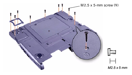
- Turn the computer upside down, and remove the
nine M2.5 x 5-mm screws labeled with a "circle B" that secure the system board
assembly to the bottom case assembly:
- Remove the three M2.5 x 5-mm screws that
secure the thermal cooling fan protective cover to the bottom case assembly.
The thermal cooling fan protective cover is located at the back on the right
side of the bottom case assembly.
- Remove the remaining six M2.5 x 5-mm screws
from the bottom case assembly.
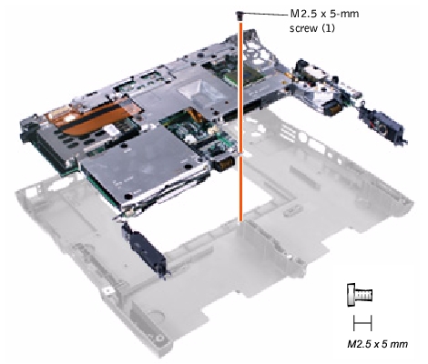
- Turn the bottom case assembly right-side up
and remove the M2.5 x 5- mm screw labeled with a white circle on the front
center of the system board.
- Remove the speakers
from the bottom case assembly.
- Pull the right side of the bottom case
assembly, next to the external headphone and microphone connectors, away from
the system board assembly as you simultaneously lift the front of the system
board assembly out and away from the bottom case assembly.
- Install the microprocessor on the replacement
system board.
- Connect the right and left speaker to the
replacement system board.
- Install the replacement system board:
- Insert the external microphone and headphone
connectors through the plastic bottom case assembly.
- Replace the nine M2.5 x 5-mm screws, starting
on the right side of the bottom case assembly.
- Replace the thermal cooling fan protective
cover, inserting the tab into the bottom case assembly and replacing the
three M2 x 4-mm screws. If you replace the screw opposite the tab first, the
other two screws are easier to insert and replace.
|
HINT: Be sure to route
cables so that they will not be crimped or pinched when the complete
assembly is put back together. |
- Replace any subassemblies that you may have
removed, including the memory modules, PCI card cage, Mini PCI card, speaker
modules, thermal cooling assembly, and hybrid cooling fan.
- Replace the palm rest assembly, the display
assembly, the hard drive, and the keyboard assembly.
- Replace the modular bay devices and any PC
Cards or plastic blanks in the PC Card slot.
|
HINT: After replacing
the system board assembly, be sure to enter the system's service tag
number into the BIOS of the replacement system board assembly.
|
- Insert the floppy disk or CD that accompanied
the replacement system board assembly into the appropriate drive, and turn on
the computer. Follow the instructions on the display screen.
|
NOTICE: Disconnect the
computer and any attached devices from electrical outlets, and remove any
installed batteries. |
|
NOTICE: To avoid ESD,
ground yourself by using a wrist grounding strap or by touching an
unpainted metal surface on the computer. |
- Remove the hard
drive assembly.
- Turn the computer over and remove the keyboard
assembly.
- Remove the display
assembly.
- Remove the palm
rest assembly.
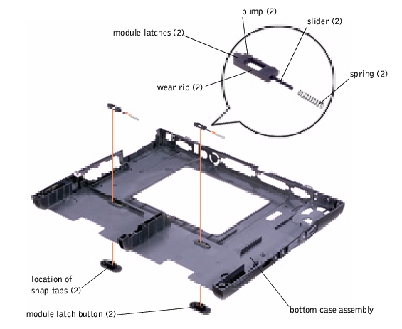
- Remove the left module latch button from the
bottom case assembly by squeezing the snap tabs.
Apply pressure to the module latch and spring while unsnapping
the snap tabs to prevent the module latch assembly from coming loose from the
case. If the module latch assembly does come loose from the case:
- Reinsert the spring onto the slider on the
module latch, and reinstall the module latch into the holding features on
the inside of the case.
|
HINT: The latch will
not function properly if the slider is oriented incorrectly.
|
- Ensure that the slider is inserted in its
respective hole, that the side of the latch with the two bumps is facing the
back of the case, and that the surface with the wear ribs is facing the
bottom of the case.
- Snap in the new latch button from the bottom of
the base, making certain its snap tabs are fully engaged in the module latch.
- Ensure that the newly installed latch moves
smoothly and freely when pushed and released.
- Repeat steps 5 through 7 for the latch on the
right side.
Back to
Contents Page
